W1 Enclosure
There are three different designs of the enclosure to incorporate three different mounting methods of the BNC connectors (J1 & J2) to the W1 printed circuit board. They are:
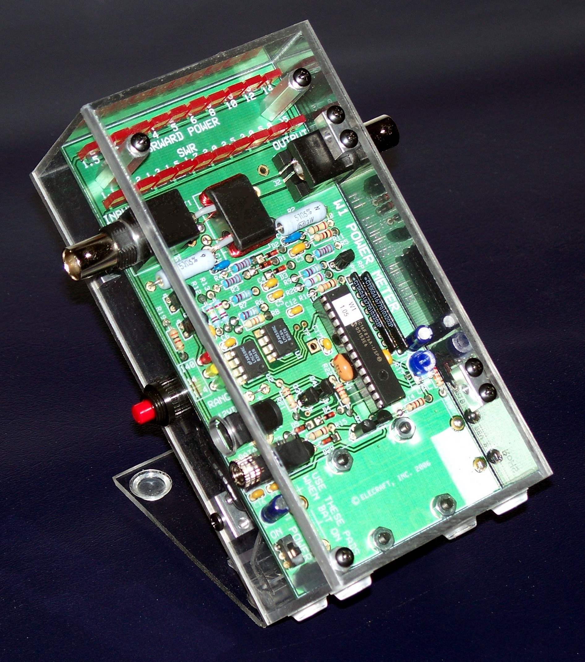
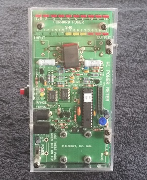
• Top mounted, right angle BNC connectors (as supplied in the W1 kit - shown above).• Bottom mounted, right angle BNC connectors (as supplied in the W1 kit)
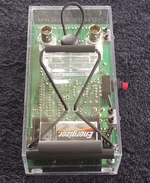
• Bottom mounted, straight through BNC connectors (as supplied by W8FGU - shown below)
The first version is slightly thicker and designed to house W1 kits already built per the Elecraft W1 manual for use without an enclosure. It is still recommended to mount the battery connector on the back of the W1 PCB for regardless of the version to make it easier to change the battery when needed. If you have not yet built the W1 (or at least not mounted the BNC connectors to the top of the PCB) it is recommended to mount the BNC connectors (right angle or straight through, whichever is desired) on the back of the PCB and install it in the bottom mounted BNC versions of the enclosure.
The power switch was also externalized to the side of the enclosure. A supplied, small push button SPST switch was mounted on the connector side of the enclosure and wired directly to the W1 PCB for power switching. The existing PCB mounted DPDT switch should be set in the off position.
All LED’s are clearly visible in the enclosure and it may be tilted to any desired angle for viewing via a separately purchased custom tilt stand mounted to the back of the enclosure. The tilt stand can be folded flat to the back of the enclosure when not in use for easy and efficient storage. Plastic feet on the bottom of the enclosure and the tilt stand, keep the enclosure from moving around on hard surfaces.

The newly designed tilt stand eliminates the velcro used in the past and is now a single piece welded to the enclosure. The tilt angle can be adjusted from 40 to 90 degrees and the angle is held in place by a loop of shock cord and a lock. The tilt panel may be folded flat to the enclosure when stored and the shock cord can be looped over the top of the stand to hold everything in place. Rubber U-channel is mounted to the bottom edge of the tilt panel and on the bottom of the enclosure and provides a more robust and sturdy grip to most surfaces. With the tilt stand folded flat, the enclosure can also be laid flat on it's back if desired.
The enclosure is constructed in two halves. These two halves are secured together via Elecraft custom 2-D fasteners and black anodized 4-40 screws. The top half contains the W1 PCB mounted to it via standoffs and the side that contains access to the power and data connector as well as the power switch. The bottom half contains the remaining side, ends and back of the assembly. Access to the inside of the enclosure is made by removing the four screws on the sides. Pulling the top half straight out of the enclosure allows for changing the battery or access to the PCB.
During initial installation, be aware that the enclosure has been designed with tight tolerances with regard to the internal size of the enclosure as it relates to the size of the W1 PCB. Keeping the mounting hardware loose until everything is lined up will help make sure the PCB is oriented properly. There is enough tolerance built into the size of the mounting holes to allow for slight adjustments during installation and insure that all of the enclosure edges are square and seams tight.
It should be noted that two hole side of the custom 2-D fasteners are drilled slightly off center. The holes in the enclosure for mounting the 2-D fasteners are aligned so that the thicker side of the 2-D fastener is positioned at the outside edge of the enclosure half.
All mounting hardware is provided for mounting the W1 into the enclosure as well as the externalized power switch. All parts are listed below:
• 3 – 1/2” hex standoffs• 3 – 4-40 lock washers
• 3 – 4-40 1/4” screws
• 4 – custom 2-D fasteners
• 15 – black anodized 3/16” screws
• 1 – SPST power switch with red button
• Top half of enclosure with power switch and standoffs mounted
• Bottom half of enclosure with tilt stand mounted
The enclosure is shipped assembled with the 2-D fasteners and black anodized screws.
installation instructions
This introduction and complete installation instructions of the W1 PCB into the enclosure can be found here.